Individual special solutions for your welding requirement.
Individual special solutions for special welding requirements
Since our foundation in 1923, IDEAL has been characterised by ever-growing success. This is the result of the continuous technical further development and quality of our machines and systems. The special machines, which are developed in accordance with the individual needs of our customers, are an important mainstay of IDEAL. After determining the customer’s problem or issue, our design department seeks and identifies the optimum technical solution, and then designs, manufactures and tests the machine until it is ready for operation. Flexibility and tailored, customer-oriented solutions are the roots of our high innovative strength here. On all machine types, the compact and robust machine design with intuitive operator guidance is oriented towards industrial usage in production. When designing the special machines, the operator is the main focus. For this reason, particular emphasis is placed on easy and ergonomic operation. Used around the world, IDEAL welding machines have been proving their quality and reliability on a day-to-day basis and have been doing so for decades.
Some product examples:
A wide range of products are manufactured using customer-specific special machine solutions from IDEAL.


Examples of the latest special solutions:
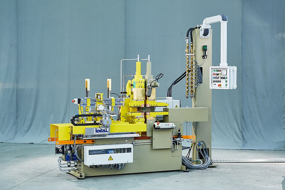
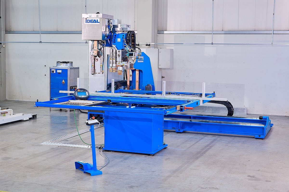
Resistance upsetting machine type WES for the production of bolster-upsetting on professional knife blades
| Max. upsetting force [kN] | 50 |
| Clamping force [kN] | 50 |
| Nominal power at 50% duty cycle | 2 x 100 = 200 kVA |

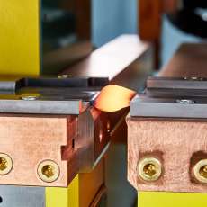
The upsetting machine heats the material and compresses it in a controlled process.
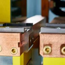
The blanks are inserted by the feed unit and clamped with a clamping device.
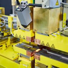
- Machine housing, carriage on both sides with roller guide for the anvil side.
- Pole plates for holding the clamping devices on the left and right.
- Linear transducer for upsetting and anvil paths
- Hydraulic compression cylinder, right, the upsetting speed can be adjusted via a manual Schiedrum flow control valve. The set values are stored by a learning program.
- Hydraulic anvil cylinder, left, the anvil speed can be adjusted via a manual Schiedrum flow control valve. The set values are stored by a learning program.
- 2 transformers water-cooled on the rear side of the machine, with double-diagonal current supply to the upper and lower electrode holder.
- The power can be adjusted between 30 and 100% via phase control within the current stage.
Hydraulic vertical clamping device.
- The clamping pressure on the left, right and centre is set with proportional pressure reducing valves.
- The depth of the left and right lower jaw can be adjusted.
- Workpiece carrier with connection for the double-diagonal current supply.
- Intensive water cooling for top and bottom electrodes.
- Pressure pieces are oscillating installations in order to balance out material thickness tolerances.
Thyristor-controlled automatic annealing system, type GAP for automatically annealing high carbon steel – consisting of:
- Infrared spectral pyrometer with integrated sensor head part, long light guide, optical head, light beam aiming device and temperature quick display unit
- Target value setting for heat-up and annealing temperature for 2 different temperature levels
- Glow current control via thyristor.
Stacking magazine for accommodating the blanks
- Stack height = 400 mm,
- With pressure balanced push unit,
- Manual filling by the operator,
- Pneumatic pushing out of the lower blank into the transfer position,
- With level control.
Pneumatic vacuum gripper for transporting the flat bars out of the magazine transfer position into the clamping device. Central electronic control unit and data storage (for double system)
- Control cabinet – stand-alone with Siemens S7 PLC control.
- With industrial PC and control panel.
The following phases of the machine operation can be adjusted:
- Clamping device: Clamping pressure through proportional pressure reducing valve
- Upsetting side, right: Manual speed via flow control valve.
Upsetting pressure through proportional pressure reducing valve:
- Anvil side, left: Speed through flow control valve
- 99 different programs can be stored under a single file no.
Fault diagnostics with clear text display Dimensions:
- Flat material min. 38 x 2.0 mm, max. 65 x 5.0 mm
- Part length 300 – 500 mm
- Handle length 100 – 140 mm
- Upsetting length max. 160 mm
- Withdrawal stroke 75 mm.
The resistance upsetting machine shown on the left is used to produce bolster-upsetting on professional knives. The machine was designed and developed by IDEAL as a special machine in accordance with customer requirements. The material pre-heated by the machine in advance is upset in the next process step. The clamping pressure and jaw distance can be adjusted to the material to be upset.
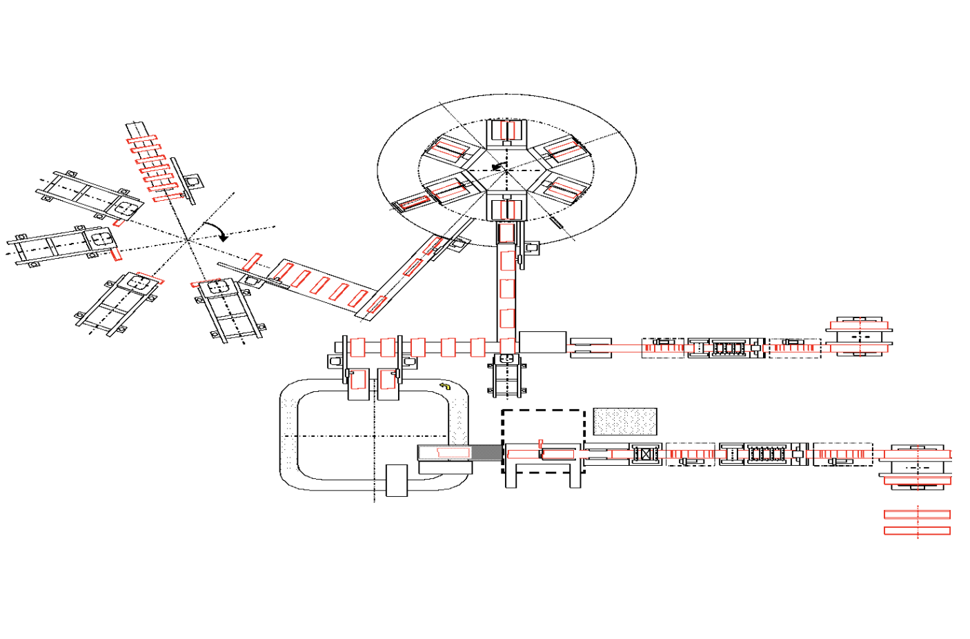
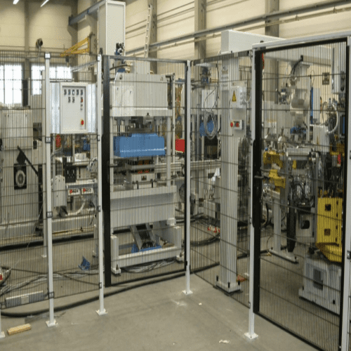
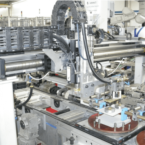
Special production line solution for particulate filters
Working together with our customer’s product development department, we developed the production line for particulate filters as an individually tailored solution. It was necessary to pay particular attention to the extremely high requirements for product quality, the reproducibility of the product characteristics and the detection of primary material and production defects. We would be delighted to assist you with the production-oriented product development.
The CSR 102 Versaweld™ jig welding machine
The machines of type CSR 102 Versaweld™ are characterised by their diversity, as well as a high degree of flexibility. With the use of the most diverse, practically oriented options, the modular construction of the machine enables the individual implementation of the customer and therefore product-specific requirements. With the CSR 102 Versaweld™ you can manufacture highly efficient three-dimensional products with a product height of up to 400mm.